Getting Started

Featured

Welcome to GardnerBender frequently asked questions page!

We’re sure you have a few questions on how to get started… Here are a few ways to browse our site:

Search Box: This is going to be the quickest way to locate exactly what you are looking for, type a few key words and select the FAQ that best matches your inquiry.

Recent Posts: This the most recent questions to be answered.

Categories: This will allow you to browse based on a general subject, and see all of the FAQ’s relevant to that topic.

If those three fail, shoot us your question and we will work to get it answered and added to our growing knowledge database.

If you have questions about the GardnerBender FAQ you can EMAIL us. We’ll be sure to add any information and/or questions to our growing database.

GardnerBender Warranty Coverage

Featured

Gardner Bender

Electrical Conduit Benders carry a 1 year limited warranty.
Hydraulic Conduit Benders carry a 1 year limited warranty.
Mechanical Conduit Benders carry a 1 year limited warranty.
Hand Conduit Benders carry a lifetime limited warranty.
PVC HotBlankets carry a 90 day warranty.
Cable Fishing equipment carry a 1 year limited warranty.
Hole Making Equipment carry a 1 year limited warranty.
Hand Tools carry a 1 year limited warranty.
Gardner Bender Test Instruments carry a 1 year limited warranty.
Wire Connectors carry a 1 year limited warranty.
Terminals & Wire carry a 1 year limited warranty.
Switches carry a 1 year limited warranty.
Cable Ties carry a 1 year limited warranty.
Staples carry a 1 year limited warranty.
Wire Management products carry a 1 year limited warranty.
Voice – Data – Video products carry a 1 year limited warranty.

The Circuit Alert and Armor Edge
These tools carry a limited lifetime warranty.

Limited
Limited means that GB warrants to the original purchasers of products from GB and Sperry Instruments authorized distributors at the time of shipment such products shall be free of defects in material and workmanship while the tool is used under normal working conditions.  Standard wear and tear, dulling over time, overloading, misuse, and acts of God are not covered under warranty. This warranty does not cover batteries, fuses, or test leads.

When a warranty claim arises, the purchaser must contact GB. If the defect comes under the terms of this limited warranty, GB will arrange , at its sole discretion, one of the following options:

-The product will be repaired at an authorized GB Service Center
-Product will be replaced

The purchaser is solely responsible for determining the suitability of GB/Sperry products for the purchaser’s use or resale, or for incorporating them into articles or using them in the purchaser’s applications. The distributor is authorized to extend the foregoing limited warranty to its original purchasers in connection with the sales of GB products, provided that such products shall not have been altered by the distributor. The distributor shall be fully responsible for any warranties the distributor makes to its purchasers which are broader or more extensive than GB limited warranty.

Lifetime Warranty
Warranty Limitation: The forgoing warranties are exclusive and are in lieu of all other express and implied warranties whatsoever, including but not limited to implied warranties of merchantability and fitness for a particular purpose. The foregoing warranties do not cover ordinary wear and tear, abuse, misuse, overloading, alterations, products which have not been installed, operated or maintained in accordance with GB/Sperry’s written instructions. Test leads, fuses, and batteries are not covered under any implied warranty. “Lifetime” of products that are no longer offered by GB will be either repaired or replaced with an item of GB Instruments choice of similar value. Lifetime is defined as 5 years after GB discontinued manufacturing the product, but the warranty period shall be at least ten years from date of purchase. Original proof of purchase is required to establish original ownership of product.

No warranty will be honored unless an invoice or other proof of purchase date is provided to Gardner Bender. Hand written receipts or invoices will not be honored.

All questions or concerns regarding our warranty should be forwarded to GardnerBender EMAIL!

Non-contact Voltage Testing (NCV)

As many of you may know non-contact voltage sensors (NCV’s) or “voltage sniffers” are strange and mysterious in how they work or in some cases don’t work. Due to the nature of this product and the science behind non-contact voltage testing, sensitivity is always a variable due to the components used and because your body completes the circuit which will affect your readings. We’re going to clear up some of the confusion behind NCV’s in this article, hopefully this will help bring you a better understanding of how they work. Below you’ll find useful tips and tricks for detecting voltage with a non-contact voltage detector.

One of the first things you want to do before you test for voltage at an outlet is disconnect any device that is connected to that specific outlet. This is largely due to the field that electricity creates.  If something is plugged into the outlet, the cord will generally increase the size of the field and make discrete detection difficult at best. The size of the field detected by a non-contact voltage detector can vary significantly in size for a variety of reasons, such as whether the box or cover is metal or plastic. Depending on the fixture (metal or plastic), the field may be greater.

For outlets in a metal box the field would be smaller and greater sensitivity would be required compared to a fixture in a plastic box where less sensitivity is required where the field is larger. GFCI outlets will generally have a larger field, making discrete detection even more difficult. The detection distance for a standard (non-GFCI) outlet, plastic cover, plastic box, should be less than 1 inch. As a result, to determine what is hot in an outlet using a (non-adjustable) voltage detector may require a technique that may not be obvious. We believe the natural way for most people to use a non-contact voltage detector is to approach the outlet directly from the front, as if one were plugging something into the outlet.

Direct

When the AC field is relatively large (plastic box/plastic outlet cover), this method will make it difficult to detect what openings of the outlet are hot. What we found works well is to approach each opening from the side.  To say it another way, if checking the outlet slot on the left side, approach the outlet from the left.  If checking the ground opening, approach the outlet from below. This is assuming the outlet is installed with the ground opening downward; if you approach the outlet from below you should be able to tell if the ground is hot.

If ground opening is toward the top, you can approach from above. We think if you try this, you will find that it is a much more accurate way to determine what parts of the outlet are hot. Remember that your body is part of the functionality of the device and completes the circuit.  If you move your finger toward the tip of the non-contact voltage detector (where the antenna is), you will find that this effects (reduces) the sensitivity.  Although not an official method of using the device, you may find this tip useful to know in differentiating a hot line, particularly when the field is large or there are several lines in close proximity.

Adjusted

Obviously, do not put your finger near the tip when checking an exposed conductor. It would also be appropriate to wear the proper protective gear for safety.Gloves

GDT-292A, 293A, 294A, & 295A Fuse Replacement

GDT-292A assembled showing 3 red insulatorsInstructions on how to replace the fuse inside the GDT-292A. These instructions will also work for the other versions of the meter: GDT-293A, 294A, & 295A. This is an older multimeter that we no longer manufacture, but we would still like to make people aware of how to replace the fuses safely without altering the multimeter in a way that could make using it dangerous. Luckily for us the customer was able to supply these pictures for others who may need help in the future.

To replace the fuse(s) open the case as previously mentioned in the manual, and remove the Printed Circuit Board (PCB) from the front cover by ONLY removing the four larger screws that are located toward the top of the meter and that are spaced to form a rectangle. The PCB and cover will now be able to separate easily.


5, What should be seen after PCB removal

DO NOT LOOSEN OR REMOVE THE FOUR SMALLER SCREWS THAT ARE LOCATED TOWARD THE MIDDLE/BOTTOM OF THE METER AND ARE SPACED 4 CM (approximately 1 1/2 inches) APART AND FORM A SQUARE.


(These four smaller screws marked in yellow in the above image hold the rotary switch in place.) DO NOT REMOVE THEM!

6, Fuses sitting on top of holders'
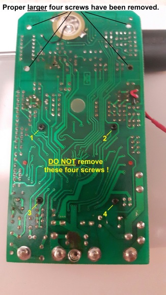
For protection against fire or injury the fuse(s) should be removed without causing damage to nearby components and should only be replaced with fuse(s) of the same specified voltage and current ratings as specified in this Operator’s Manual.

7, Fuses removed for testingRefer to the two photos above. One black and three red rubber insulators surround the four jacks that the leads can plug into. The insulators are held in place against the PCB by the front cover. Upon dis-assembly one or more of the colored insulators may get stuck in the cover (in this dis-assembly one red and one black insulator were stuck to the cover). For ease of re-assembly, the stuck insulators can easily be pressed out of the cover and put into place on the PCB (wide end toward the PCB) as the two red ones in these photos are. Just remember, the BLACK rubber insulator goes on the post of the PCB labeled “COM” (of course). These insulators ensure a snug fit of the leads without using split-tip leads that lose their tension over time.

HGT6120 – AFCI Circuit Breakers

There were concerns that the HGT6120 would not function correctly on an AFCI Circuit Breaker, causing the breaker to trip as soon as you plugged our tester in. AFCI translates to Arc-Fault-Circuit-Interrupt and on many new models comes equipped with a self-test. We went ahead and started testing to see what the issue was while using the HGT6120 and all of our other GFCI circuit testers on AFCI circuits. During testing we used many different AFCI circuit breakers from multiple vendors. We were not able to find any issues while testing and we didn’t have any problems using any of our circuit testers on the new AFCI circuit breakers.

There is one other theory as to why this is happening on AFCI circuit breakers. It could be that the circuit breakers being tested are older and more prone to tripping. Circuit breakers are like most switches and over time they wear down. If this is the case and they aren’t functioning properly, they may need to be inspected and replaced. In any case, a licensed electrician should be involved to determine the root cause of the problem.


WiFi Inspection Camera (WIC-100) Troubleshooting

If your phone is not displaying the video feed you can try these steps to resolve the issue:

1 – You’ll want to first shut down the application.

2 – Turn the WiFi Camera off and then back on. (Make sure that you feel the click and that the light goes all the way off)

3 – Check to make sure that your device has established a connection with the WiFi Camera.

4 – Re-open the application.

If the above steps failed to resolve the issue: Reset the WiFi Camera by holding the reset button down 5 seconds. Perform this action while the camera is turned on. The reset button can be found next to the power wheel. See below picture.

WIFI 2

WiFi Inspection Camera (WIC-100) Battery Install

The battery door is located on the bottom of the handle. Using your thumb; push the door away from the housing towards the rubber grip. Once the battery door has been removed the battery cartridge will slide out. Install four double AA batteries into the cartridge and replace it back into the handle and install the door.

Fuse & Test Lead information for obsolete and current meters.

Meter Fuses and Leads
Model Available Leads Fuse NOTES
530 OBSOLETE F-4 F-6
3005 OBSOLETE NA
3021 OBSOLETE NA
3121 OBSOLETE NA
3122 OBSOLETE NA
3123 OBSOLETE NA
3124 OBSOLETE NA
3125 OBSOLETE NA
3131 OBSOLETE F-22 F-25
3165 OBSOLETE NA
3166 OBSOLETE NA
3301 OBSOLETE NA
3302 OBSOLETE NA NO TEST LEADS AVAILABLE
3315 OBSOLETE NA
4102 OBSOLETE NA
4105 OBSOLETE NA
6017 OBSOLETE NA
6030 OBSOLETE NA
6300 OBSOLETE NA
3001B OBSOLETE NA
3132MOV OBSOLETE NA
3135P OBSOLETE F-8 F-11
3322A OBSOLETE NA
620C OBSOLETE F-7 F-12
ADM-18 TL-42 F-27
ADM-28 TL-42 F-22 F-25
ADM-88 TL-42 F-21 F-20
AV-1A OBSOLETE NA
CM-201 OBSOLETE F-16
DM-10 TL-42 NA
DM-1000 OBSOLETE F-14
DM-12 TL-42 F-2
DM-2000 OBSOLETE F-14
DM-210A TL54
DM-3000 OBSOLETE F-14
DM-3010 TL-42 F-11
DM-350A TL54
DM-360A TL54 F-7
DM-370A RL54 F-7
DM-4000A TL-42 F-17
DM-4100A TL-42 F-17
DM-4300A TL-42 F-17
DM-4400A TL-42 F-7
DM-5300 TL-42 F-24 F-25
DM-6100 TL-42 F-20 F-22
DM-6200 TL-42 NA
DM-6200 (OLD) TL-42 F-20 F-22
DM-6250 TL-42 NA
DM-6300 TL-42 F-20 F-22
DM-6400 TL-42  10 Amp  1 Amp
DM-6450 TL-42 10 Amp 1 Amp
DM-6500 OBSOLETE F-13
DM-6510 TL-42 F-14
DM-6600 TL-42
DM-6650T TL-42
DM-6910 TL-52 F-14
DM-7010 TL-42 F-11
DM-7100 TL-42 F-23 F-7
dm5300 TL-58 f24,f25
DM-7A TL-42 F-24
DM-8010 TL-42 F-14
DM-8100 TL-42 F-20 F-21
DM-8200 TL-42 F-20 F-21
DM-8300 TL-42 F-20 F-21
DM-8400 TL-42 F-21 F-20
DM-8500 TL-42 F-20 F-21
DM-8600 TL-42 F-20 F-21
DM-8700 TL-42 F-21 F-20
DM-8A TL-42 F-22 F-25
DM-9100 NA F-29 F-30
DM-9500 TL-42 F-7 F-26
DM-9A NA F-2
DP-300 OBSOLETE F-8
DP-306 OBSOLETE F-10
DP-310 OBSOLETE F-8
DP-316 OBSOLETE F-10
DSA-1000 OBSOLETE NA No battery or charger available.
DSA-1001 TL-52 NA
DSA-1003TRMS TL-52 NA
DSA-1010 TL-42 NA
DSA-1020TRMS TL-42 NA
DSA-2002P TL-42 NA
DSA-2002R TL-42 NA
DSA-2003 TL-42 NA
DSA-2007 TL-52 NA
DSA-2007A TL-52 NA
DSA-2009 TL-42 NA
DSA-2415 TL-42 NA
DSA-400 TL-52 NA
DSA-440 TL-52 NA
DSA-440T TL-52 NA
DSA-450TRMS TL-52 NA
DSA-500A TL-42 NA
DSA-540A TL-42 NA
DSA-600 TL-42 NA
DSA-600P TL-42 NA
DSA-650TRMS TL-42 NA
DSA-660 TL-42 NA
DSA-680TRMS TL-42 NA
DSA-700 TL-52 NA
DSA-710 TL-52 NA
DSA-720 TL-52 NA
DSA-730 TL-52 NA
DSA-740 TL-52 NA
DSA-750 TL-52 NA
DSA-760 TL-52 NA
DSA-7610 TL-42 NA
DSA-770 TL-52 NA
DSA-780 TL-52 NA
DT-40A OBSOLETE NA
EZ-6111 OBSOLETE F-8
EZ-6221 OBSOLETE F-8
GCM-221 RTL-200
GCM-306 OBSOLETE GF0306
GCM-307 OBSOLETE
GCM-500 RTL-200
GCM-600 RTL-200
GCM-620 RTL-200
GDT-190 RTL-103 F-14
GDT-192 NA GF2050
GDT-193 NA GF2050
GDT-194 NA GF2050
GDT-200 RTL-103
GDT-292A RTL-200
GDT-293A RTL-200
GDT-294A RTL-200
GDT-295A RTL-200
GDT-311 RTL-300 NA
GDT-3190 RTL-300 NA
GDT-3200 RTL-300 NA
GDT-820 NA
GDT-830 NA GF2050
GMT-17 NA GF017P
GMT-312 RTL-108
GMT-318 RTL-108
GMT-319 RTL-103
GMT-41 RTL-103
HSP-10A TL-34 F-7
HSP-5A TL-34 F-16
OHM-150 OBSOLETE NA SNAP 6
OHM-300 OBSOLETE NA SNAP 6
OHM-525 OBSOLETE NA SNAP 6
SDC-701 OBSOLETE NA SNAP 7
SDM-410 OBSOLETE F-7
SDM-460 OBSOLETE F-7
SJ-100A OBSOLETE NA
SJ-50A OBSOLETE NA
SP-10A TL-34 F-7
SP-152A TL-56 F-7
SP-142  OBSOLETE 500MA
SP-15A TL-34 F-7
SP-160 OBSOLETE F-1
SP-170B TL-56 F-18
SP-250B TL-56 F-19
SP-5A TL-34 F-16
SP-6A TL-34 F-16
SPM-2011 OBSOLETE NA
SPM-2012 OBSOLETE NA
SPR-1030 OBSOLETE NA SNAP 10
SPR-300+ TL-52 F-1
SPR-311 OBSOLETE F-1 SNAP 8 PLUS
SPR-931 TL-42 NA SNAP 9
SR-150 OBSOLETE NA
SR-150 OBSOLETE NA SNAP 5
SR-25 OBSOLETE NA SNAP 5
SR-300 OBSOLETE NA SNAP 5
SR-50 OBSOLETE NA SNAP 5
TD-2608 TL-52 F-1
TD-6 OBSOLETE NA
Fuse Specs
Part Number Size Voltage Amperage Description
F-1 1/4″x 1 1/4″ 250V .5A fast acting, glass
F-2 5mm x 20mm 250V .1A fast acting, glass
F-3 1/4″ x 1 1/4″ 250V .1A fast acting, glass
F-4 1/4″ x 1 1/4″ 250V .02A fast acting, glass
F-6 1 3/32″X 1 1/2″ 600V .25A Bussman KTK
F-7 5mm x 20mm 250V .5A fast acting, glass
F-8 5mm x 20mm 250V .3A fast acting, glass
F-9 1/4″ x 1 1/4″ 250V .25A Cold resistance
F-10 5mm x 20mm 250V .75A fast acting, glass
F-11 5mm x 20mm 250V 2A fast acting, glass
F-12 1/4″ x 1 1/4″ 250V 1A fast acting, glass
F-13 6.4mm x 30mm 250V .5A Arc Quenching Silicon Filter
F-14 5mm x 20mm 250V .2A fast acting, glass
F-15 6mm x 30mm 250V 2A fast acting, glass
F-16 5mm x 20mm 250V .25A fast acting, glass
F-17 5mm x 20mm 250V .8A
F-18 6.35mm x 30mm 250V .5A fast acting, glass
F-19 5.2mm x 20mm 250V 1A fast acting, glass
F-20 13/32″x 1 1/2″ 600V 20A Bussman KTK
F-21 6.3mm x 25mm 600V .5A Ceramic
F-22 5mm x 20mm 250V .5A Fast acting, ceramic
F-23 1/4″ x 1 1/4″ 600V 10A Fast acting, ceramic
F-24 1/4″ x 1 1/4″ 600V 2A Fast acting, ceramic
F-25 1/4″ x 1 1/4″ 600V 10A Fast acting, ceramic
TL-42, TL-52, TL58 leads are interchangeable.
Best locations to send customers for fuses is Parts Express 1-800-338-0531 http://www.partsexpress.com or Newark 1-800-463-9275 http://www.newark.com
We do not have any cases available for the testers.
We have no replacement parts available for the testers.  If the unit is in need of repair, contact http://www.daviscalibration.com or http://www.transcat.com for closest locations.
For Gardner Bender Test leads, http://www.acehardwareoutlet.com stock them.  For Sperry test leads http://www.delcity.net has them.We do not have the charger or batteries available for the DSA-1000 clamp meter.The specs for the SBC-1 charger are 9 VDC 25mA

Battery Type by Product

Product Number Battery Type Quantity
CAM-10 LR-44 2
GCV-3206 LR-44 2
GCT-3304 AAA 2
GVD-3504 AAA 1
GVD-3504 LR-44 2
GET-4220K TRANSMITTER AA 2
GET-4220K RECEIVER LR-44 4
GET-4110K TRANSMITTER AA 2
GET-4110K RECIEVER LR-44 4
GMT-312 AA 1
GMT-318 AA 1
GMT-319 AA 2
GDT-311 9V 1
GDT-3190 9V 1
GDT-3200 AAA 2
GCM-500 AA 1
GCM-221 AAA 2
GVC-1000 AAA 3
GCT-204 AAA 2
GFT-200 AA 2
GVD-504A LR-44 2
GVD-505A LR-44 2
GPD-902 9V 1
GVC-300 LR-44 2
GET-207 A27(12V) 1
GCV-206 LR-44 2
GET-1200 9V 1
GMT-12 AA 1
GMT-18 AA 1
GMT-19 AA 2
GDT-185 LR-44 2
GDT-190A 9V 1
GDT-200A 9V 1
GDT-292A 9V 1
GDT-293A 9V 1
GDT-294A 9V 1
GDT-295A 9V 1
GCM-500 AA 1
GCM-221 AAA 2
GCM-600 9V 1
GCM-620 9V 1
GSS-510A LR-44 4
GSS-500A LR-44 4
GCT-304A AA 2
GAT-503 AAA 1
GVD-504LV LR-44 2
GAT-550 LR-44 2
GMT-41P AA/9V 1 EACH
GET-4100R 9V 1
GET-4100T 9V 1
GET-4000 9V 1
GET-4010 9V 1
GET-4040 9V 1
GET-6000 9V 1

Duct Seal Usage Rating Outdoors or in Vehicles.

The temperature usage range for Duct Seal is 25 to 120 degrees F and it has a tolerance range of -30 to 175 degrees F. This means the Duct Seal should be applied between 25 to 120 degrees F. Duct Seal is used and designed primarily to plug holes around conduit mostly inside buildings but is also used outside on service entries. There is a tendency to dry on the surface when exposed to weather. There is material in these locations that are dry but still maintain a seal after 20 years. As far as use in vehicles, there shouldn’t be a problem unless the vibration causes the material to not adhere to the surface.

Duct Seals Reaction to Gas Vapors and Liquids.

Duct Seal is resistant to gas vapors however, if condensation of gases occurs then it becomes an issue. Liquid gases contacting duct seal can soften the material. Gases themselves are not the problem but liquid formed by condensation over extended periods could be an issue. Duct Seal is not meant to be used outdoors.